IP CORE FAMILY

Wireless PHY

A complete 802.11a Wi-Fi receiver physical layer for FPGA: from baseband I/Q samples to recovered data bits. Packet detection, carrier-frequency-offset correction, OFDM demodulation, channel equalization, soft demapping, and Viterbi decoding, generated as bit-exact RTL and proven by recovering a MATLAB-generated standard waveform with zero bit errors. It is deployed on an ADALM-Pluto software-defined radio, split across the FPGA fabric, the embedded ARM, and the host, and recovers the transmitted image over the air on every data rate.

FLAGSHIP

A receiver that recovers the standard, bit for bit

The receiver was driven with waveforms produced by the MATLAB WLAN Toolbox, passed through a 12-bit ADC model, and decoded by the fixed-point hardware. Every figure below is a measured tool result: a Vivado place-and-route timing summary, a utilization report, or a bit-level cocotb cross-validation.

0 errors
MATLAB 802.11a waveform recovered bit-for-bit, 38,400 bits MEASURED
162.7 MHz
Receive clock, full receiver PHY, place-and-route on a Zynq-7010 MEASURED
54 Mbps
802.11a line rate sustained, the highest data rate (64-QAM, rate 3/4) MEASURED
8 / 8
Data rates decoded bit-exact, BPSK through 64-QAM MEASURED

Characterized, then deployed three ways

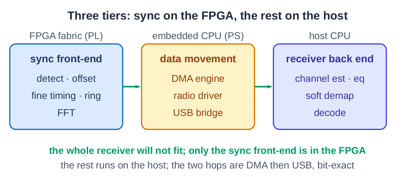
The full receiver PHY is characterized as a complete place-and-route on a Zynq-7010, and separately on a Zynq UltraScale+ RFSoC for clock headroom. On the ADALM-Pluto itself the full PHY does not fit alongside the radio's own interface logic, so the on-radio deployment is split across three tiers: the synchronization front-end in the FPGA, the rest on the host, and validated over the air. Every figure is a real measured result.

ResultValueProvenance
Receive clock, full PHY (Zynq-7010 place-and-route)162.7 MHzVivado P&R, dual-clock MEASURED
Receive clock, Zynq UltraScale+ RFSoC (characterization)309.6 MHzVivado Design Timing Summary MEASURED
Logic, full PHY (Zynq-7010 place-and-route)8,514 LUT / 8,233 FFVivado utilization MEASURED
Delivered image over the air, all 8 modes100% bit-exact831 / 832 raw per packet, a channel hit MEASURED
Continuous decode on the Pluto, 90 s run1390 / 1390every packet, no reset MEASURED
End-to-end recovery, MATLAB waveform to fixed-point receiver0 errors / 38,400 bitsbit-level cross-validation MEASURED

The full PHY (about 8,500 logic cells) plus the radio's interface logic (about another 8,500) exceed the 17,600 on the Pluto, so the on-radio deployment keeps the rate-critical synchronization front-end in the FPGA and runs the heavier back end on the host, bridged by DMA then USB. It runs continuously: it consumes an unbroken stream of baseband samples, finds each packet on its own, and decodes one after another with no reset, recovering the transmitted bits exactly across all eight data rates.

Three tiers: synchronization front-end and FFT in the FPGA, data movement on the embedded processor, the receiver back end on the host
On the Pluto the receiver is split across three tiers: only the synchronization front-end fits the FPGA, the rest runs on the host, bridged by DMA then USB.
INSIDE

What the receiver does

The input is the stream of baseband I/Q samples that an RF front end (the AD9363 on the ADALM-Pluto) delivers after down-conversion, not the antenna signal itself. The receiver turns that stream into clean data bits in four stages, each mirroring a step of the 802.11a standard.

Synchronize

detect · time · CFO

Schmidl-Cox packet detection and a matched filter on the training sequence find each packet in the sample stream, lock fine symbol timing, and estimate and correct the carrier frequency offset before demodulation.

Operationcontinuous, self-rearming

Demodulate & equalize

FFT · channel est · EQ

A 64-point FFT converts each OFDM symbol to the frequency domain. The long training symbols give a channel estimate, and every data subcarrier is equalized with its own per-subcarrier correction.

OFDM FFT64-point, one sample/clock

Demap & deinterleave

soft LLR · deinterleave

Each equalized subcarrier is soft-demapped to log-likelihood ratios with channel state weighting, then deinterleaved and depunctured to reconstruct the coded bit stream the decoder expects.

ModulationBPSK / QPSK / 16- / 64-QAM

Decode & descramble

Viterbi · descramble

A Viterbi decoder for the rate-1/2 K=7 convolutional code runs in its own clock domain, crossed by a small asynchronous FIFO, followed by descrambling to deliver the original payload bits.

FECViterbi, K=7

Need a different standard or a transmit chain (802.11n, a custom OFDM link)? The same flow generates and re-verifies new configurations. See IP customization.

SEE IT RUN

Real captured signals, replayed in your browser

The receiver was run over the air on two antennas. The link analyzer below replays that real on-silicon capture, no hardware needed. As the data rate climbs, the constellation sharpens from BPSK to 64-QAM, the channel response and spectrum update, and the transmitted image rebuilds as each packet is decoded.

Live link analyzer: 64-QAM constellation, channel response, spectrum, and the recovered image, from real captured 802.11a data
Launch the interactive demo

Over the air on two antennas the link recovers the image bit-exact on every data rate, and across a continuous run it decoded every packet with no errors. The analyzer above replays the actual captured samples in your browser, with no server and no radio attached.

Case study: an AI-generated Wi-Fi receiver

How a complete 802.11a receiver went from a MATLAB reference design to bit-exact FPGA hardware that no one wrote by hand, and how every layer was checked against the standard. The design retrospective covers the deployment: the three-tier split (FPGA, processor, host), the bring-up ladder, and the two bugs that only appeared on silicon.

Read the case study
Request datasheet & evaluation