MATLAB ships a reference design called "Image Transmission and Reception Using 802.11 Waveform and SDR". It gives a full 802.11a transmit and receive chain: cut an image into packets, modulate them into a Wi-Fi waveform, and on the receive side synchronize, error-correct, and reassemble the original image exactly.
Re-implementing that receiver on an FPGA by hand, translating the MATLAB line by line into RTL or HLS C, is tedious enough that the project sits on the shelf for years. Instead, we pointed our algorithm-to-silicon flow at the reference design and let it generate the receiver directly. In a few days the whole 802.11a receive chain went from a mathematical model to synthesizable Verilog, targeting the small Zynq-7010 FPGA on an ADALM-Pluto software-defined radio.
That raises a fair question. If no engineer wrote the hardware by hand, why should anyone trust that it is correct? This is the part worth explaining.
Generated in layers, checked at every layer
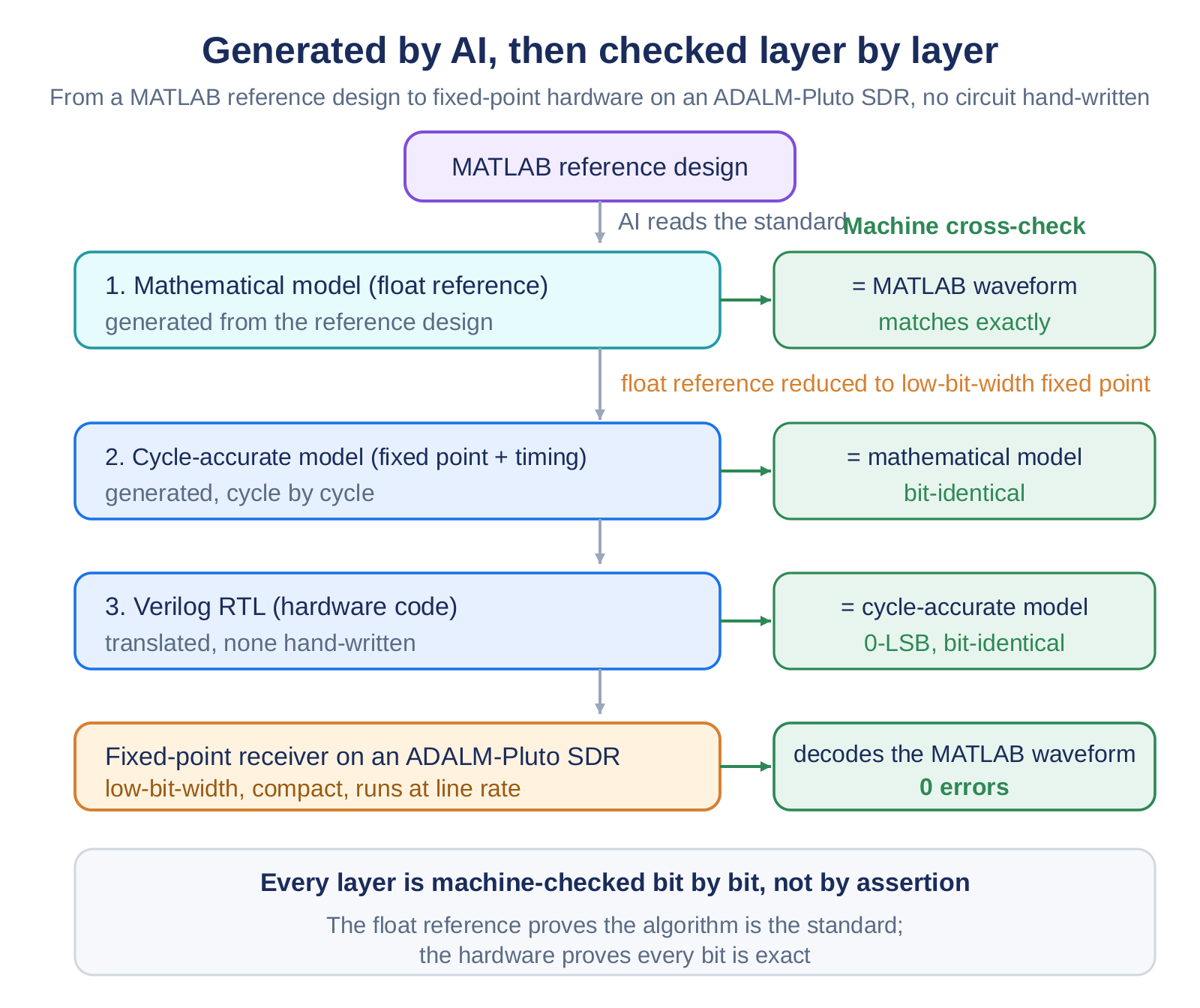
The flow does not write hardware in one leap. It builds the receiver in three layers and has a machine check each layer against the one above it:
- A golden mathematical model: a floating-point reference whose waveforms match the MATLAB standard toolbox exactly. This pins down "the algorithm is the standard".
- A cycle-accurate model: the reference reduced to low-bit-width fixed point with cycle-by-cycle hardware timing, checked bit-for-bit against the mathematical model.
- The Verilog RTL: translated from the cycle-accurate model and checked, bit-for-bit, against it.
What matters is that every adjacent pair of layers is reconciled automatically, bit by bit, rather than by assertion. That the code was generated is almost beside the point. Fixed-point hardware cannot match floating point in the last decimal place, and it does not need to. Its one hard target is to recover the transmitted bits exactly.
What the receiver does
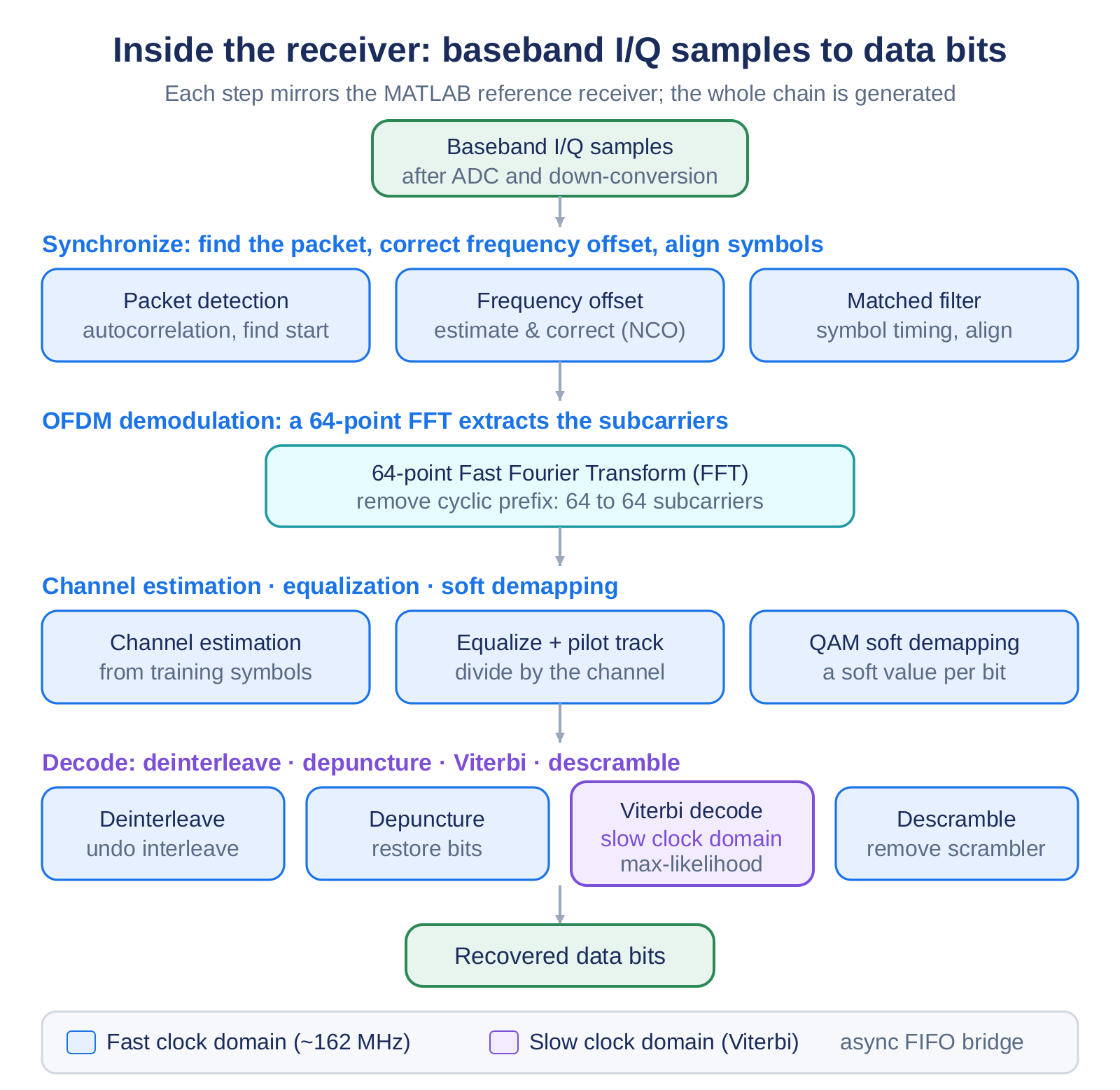
The input is the stream of baseband I/Q samples the RF front end (the AD9363 on the Pluto) produces after down-conversion, not the antenna signal. The receiver turns that stream into clean data bits, mirroring the 802.11a standard step for step: it detects each packet and corrects the carrier frequency offset, runs a 64-point FFT to demodulate each OFDM symbol and equalizes every subcarrier, soft-demaps the symbols to likelihoods and deinterleaves them, then Viterbi-decodes the convolutional code and descrambles to recover the payload.
What the signal looks like
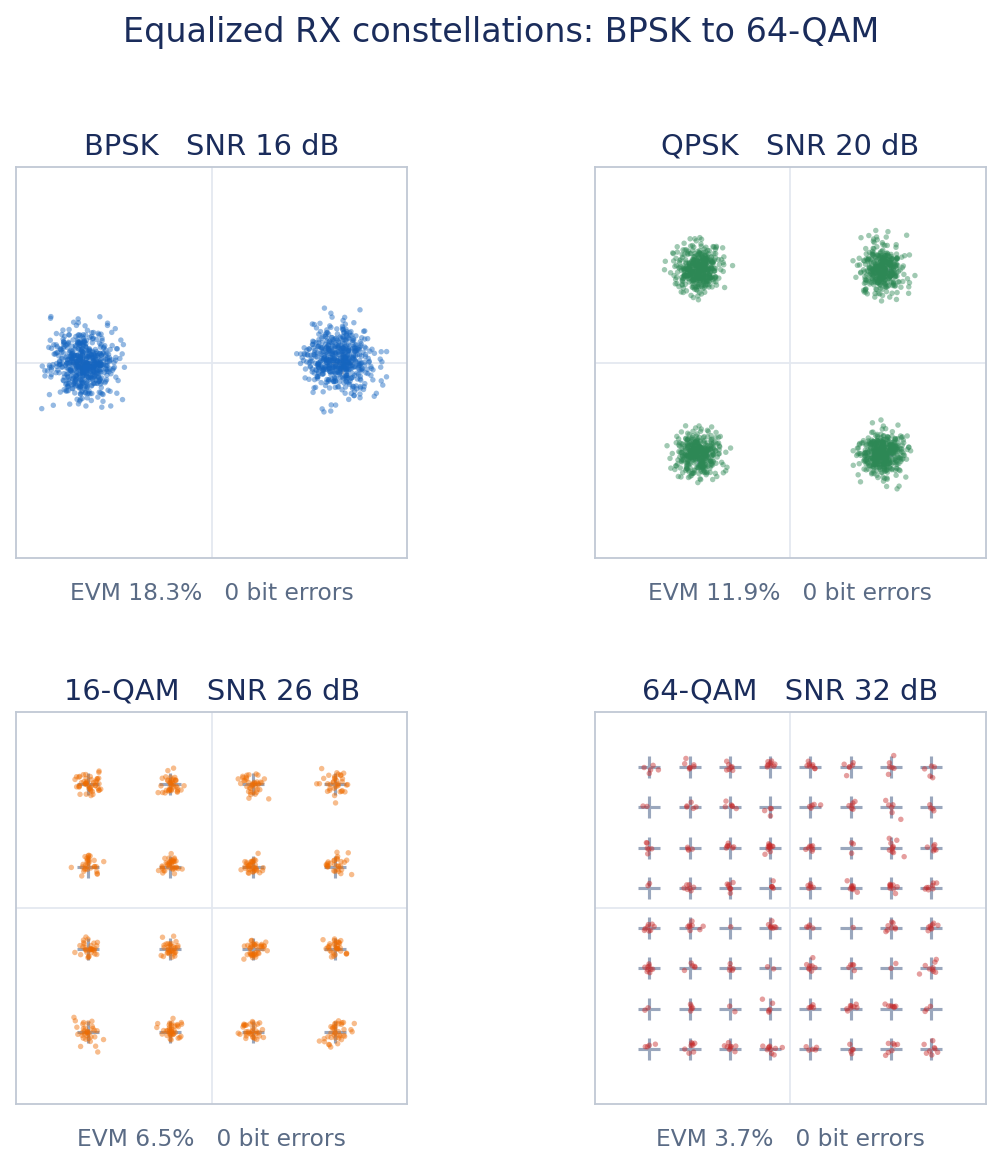
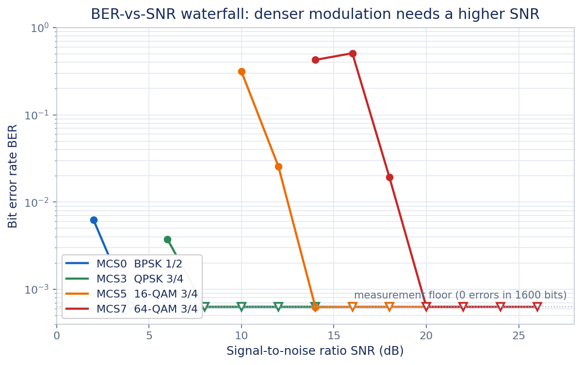
Two measurements describe the link itself. The transmit spectrum shows the OFDM signature: 64 subcarriers filling roughly 16.6 MHz inside the 20 MHz channel. The bit-error-rate curves show how each modulation behaves as the channel degrades: denser constellations carry more bits but need a higher signal-to-noise ratio to stay clean.

The proof: a picture in, the same picture out
The most convincing test is end to end. We take waveforms generated by the MATLAB WLAN Toolbox, pass them through a 12-bit ADC model, and decode them in the fixed-point hardware. Across 24 packets and 38,400 bits, the receiver returns the transmitted bits with no errors. The transmitted image is reassembled exactly.

See it run on real captured signals
The same picture-in, picture-out test was run over the air on two antennas, and the captured samples were saved straight off the radio. The link analyzer below replays that real on-silicon capture in the browser, with no hardware attached. As the data rate climbs from BPSK to 64-QAM, the constellation sharpens, the channel response and spectrum update, and the image rebuilds as each packet is decoded.
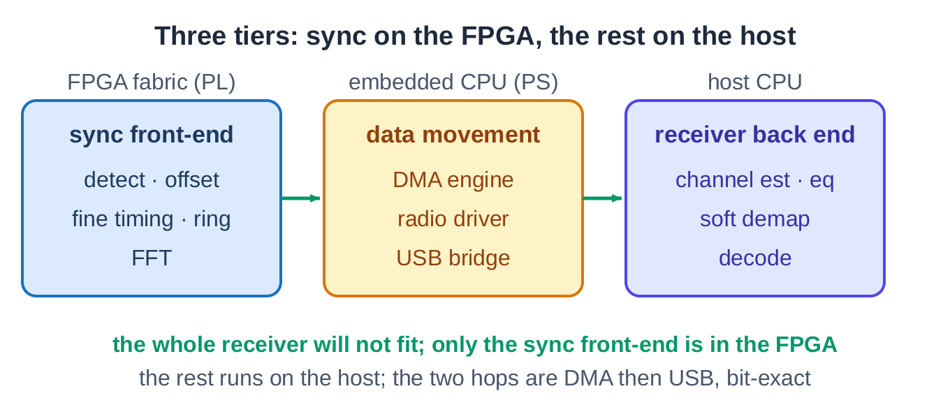
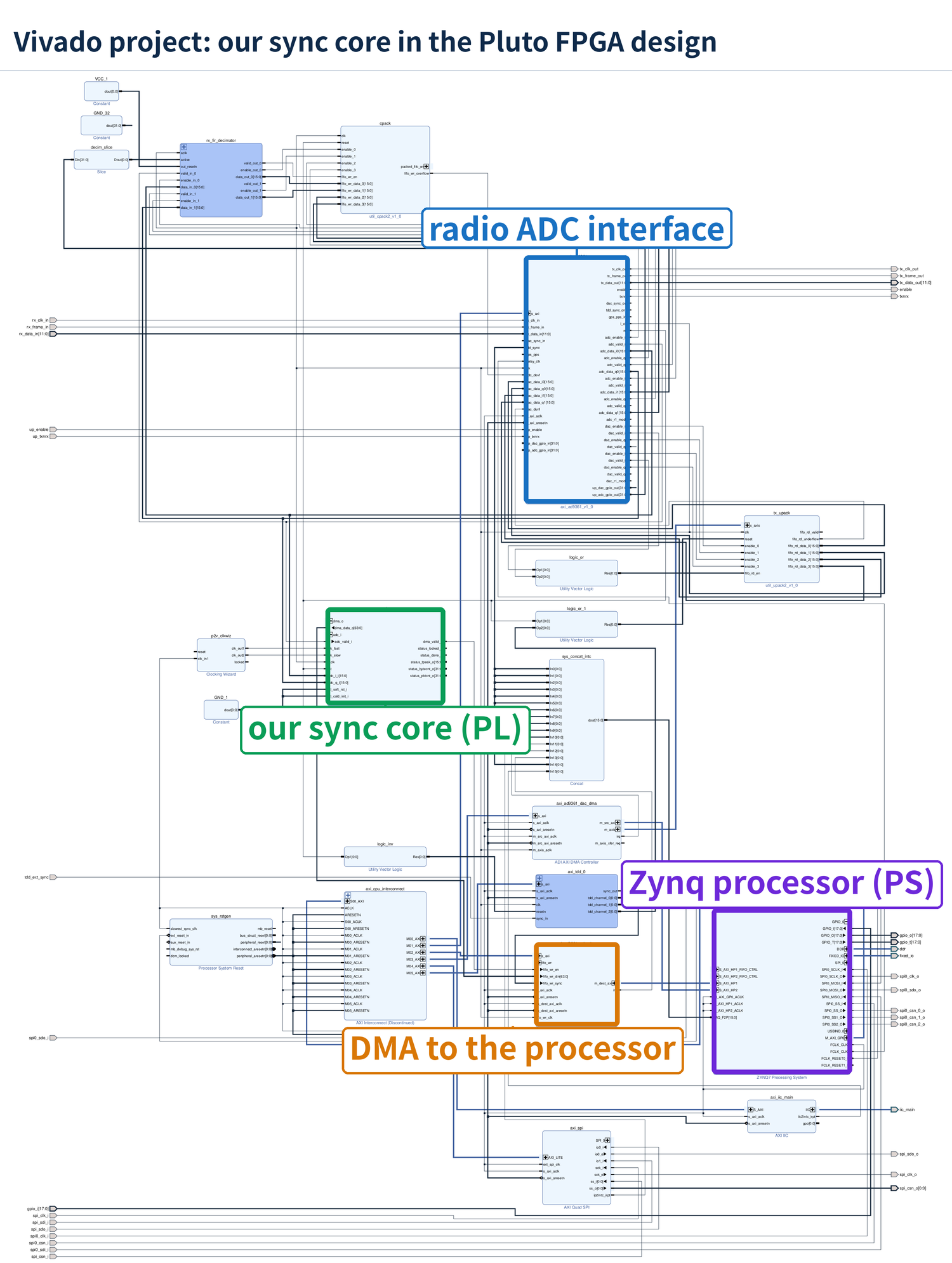
Deployed across three tiers to fit the Pluto
The receiver PHY is small and portable. As a full place-and-route on a Zynq-7010 it closes a 162.7 MHz receive clock and uses 8,514 LUTs, 8,233 flip-flops, 5.5 block RAMs, and 43 DSP slices; characterized on a Zynq UltraScale+ RFSoC the same design reaches 309.6 MHz, showing clock headroom for faster standards.
But the ADALM-Pluto's chip is tiny. The full receiver (about 8,500 logic cells) plus the radio's own interface logic (about another 8,500) do not both fit the 17,600 cells on the device. So the deployment is split across three tiers: the rate-critical synchronization front-end and FFT stay in the FPGA fabric (the programmable logic, PL); the embedded ARM processor (the processing system, PS) moves the data with its DMA engine, radio driver, and USB bridge; and the heavier back end (channel estimation, equalization, soft demapping, and Viterbi decoding) runs on the host. The FPGA hands the processor frequency-domain symbols over DMA, the processor streams them to the host over USB, and both ends run the same reference model, so the split stays bit-exact end to end.
Run that way over the air on two antennas, the delivered image comes back bit-exact on every data rate. Over a cable a continuous 90-second run decoded every packet (1,390 of 1,390); over the air the raw per-packet rate was 99.88% (831 of 832), the single miss a real wireless channel hit rather than a host drop, which the protocol retransmits so the image stays perfect.
Why this is repeatable
Nothing here is specific to one image or one packet. The same flow takes a signal processing reference (a different standard, a transmit chain, a custom OFDM link) and generates a verified receiver or transmitter the same way, with the same bit-exact checks at every layer. The receiver is available as the Wireless PHY IP core; the method behind it is available as a design service.