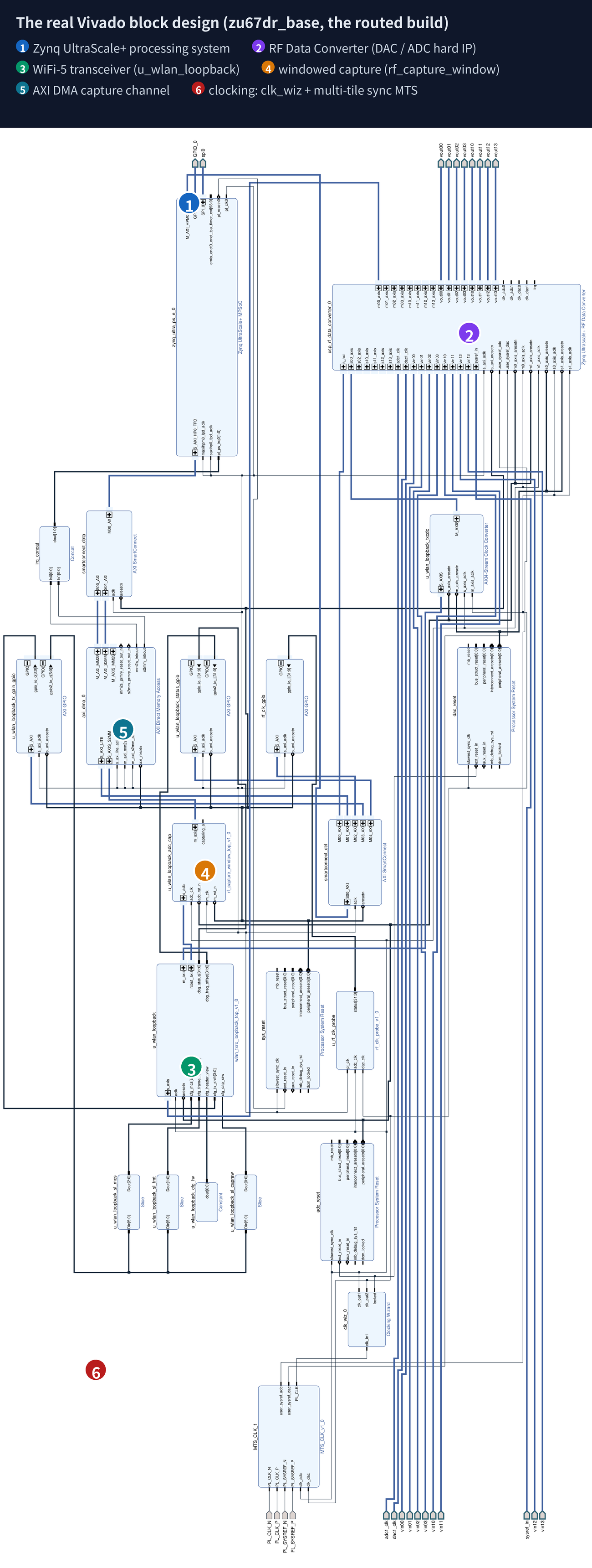
A Wi-Fi 5 transceiver is a large piece of signal processing: frame detection, frequency correction, an FFT, channel estimation, demapping, deinterleaving, a Viterbi decoder. The reference implementation we started from was written for a vendor evaluation board. Our target was a custom board with a newer generation of data converters, a different interface width, and no board support package.
The transmit output goes into an SMA cable and straight back into the receive input on the same device, so the entire radio link is one cable. That makes the experiment honest: if the payload comes back wrong, the fault is ours.

What had to be bridged
Two gaps separated the reference design from our hardware. The converters are a newer generation, which adds configuration options that did not exist on the reference platform, and whose defaults are not chosen for our use case. And the interface widths do not match: the reference core moves eight samples per clock, while our converter interface carries two, so a small reshaping block sits on each side, serialising on transmit and reassembling on receive.

The first wall: every simulation passed and the board did not
The receiver was verified in simulation against a golden reference: 1037 payload bytes, bit-exact. A second, independent simulation of the synthesized netlist agreed. On the board, the status register reported a successful decode.
That status word was the trap. Asked for the actual payload bytes rather than the flag, the board returned 29 of them. Worse, the result moved: adding a little capture logic changed the placement, and the reported rate changed with it.
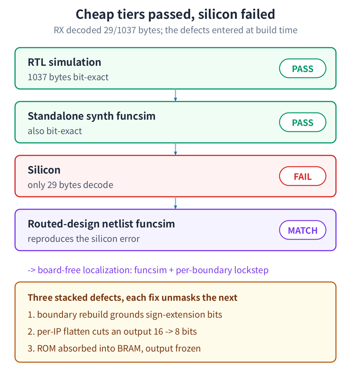
The move that broke it open was to stop simulating the source and start simulating what the tools had actually built. The netlist extracted from the placed and routed design reproduced the board's failure byte for byte. From that point the investigation needed no hardware at all: compare that netlist against the behavioural model, boundary by boundary, and walk inward.
Three separate defects were stacked inside, each one hidden by the one before it. Sign extension bits tied to ground. An output width cut from sixteen bits to eight. A lookup table absorbed into block memory whose output then froze while its address kept advancing.
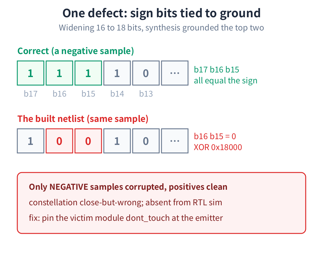
None of these transforms exist in the source, which is why source-level simulation is structurally blind to them. All three were corrected at the point where the design is emitted, not by hand-editing generated code. The board then returned all 1037 bytes with no errors.
The second wall: headers perfect, data noise
With the link running, a stranger symptom appeared. Frame headers decoded correctly every time, with format, rate, length and checksum all consistent. The data behind them was noise, and different noise on every capture.
Five explanations were proposed, built, and refuted in turn. A slip in the width converter. Preamble degradation. A low signal to noise reading, which turned out to be a measurement error. Transmit gain. Clock wander. Each round cost a full rebuild.
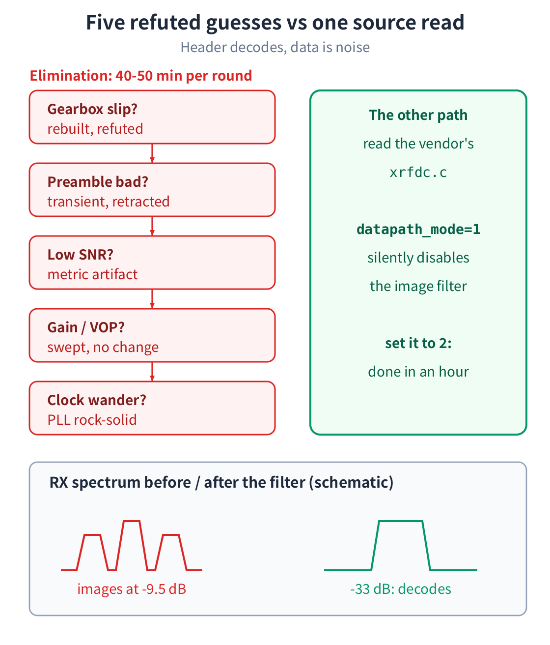
The cause was a single configuration field. On this converter generation, the default data path mode bypasses the filter that suppresses the image produced when a complex signal is converted to a real output. Unsuppressed, that image sits either side of the wanted signal and widens it to roughly three times its proper occupied bandwidth. Robust, low-order header symbols survive the interference. Dense data symbols do not, and because the interference phase differs from capture to capture, the corruption looks random.
Changing that one field pushed the images from 9.5 dB below the signal to 33 dB below it, and the data decoded on the next capture.
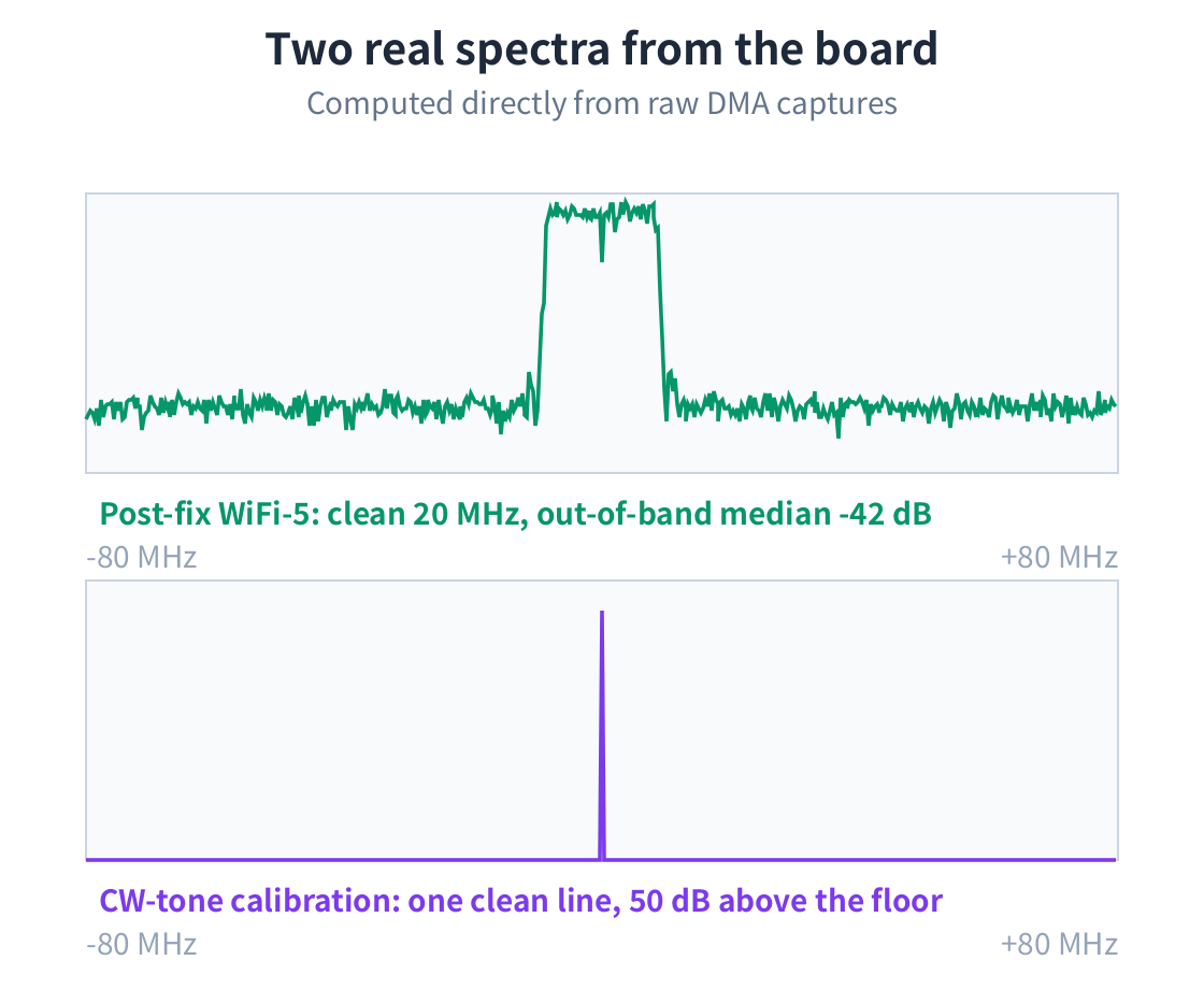
A related correction belongs with it. In a single-converter loopback at a real intermediate frequency, the receiver's local oscillator has to run at the opposite sign to the transmitter's. With the same sign the receiver locks onto the mirror image and the subcarriers come out transposed. That one was settled by reading mixer references rather than by experiment.
What the finished link measures
All 24 combinations of frame format and modulation rate decode on a single bitstream, selected at runtime with no rebuild and no reflash. Verification went past the status flag: the receiver's decoded output was captured to the host and compared against an ideal reference through the same offline chain, symbol decisions first and payload bytes after.
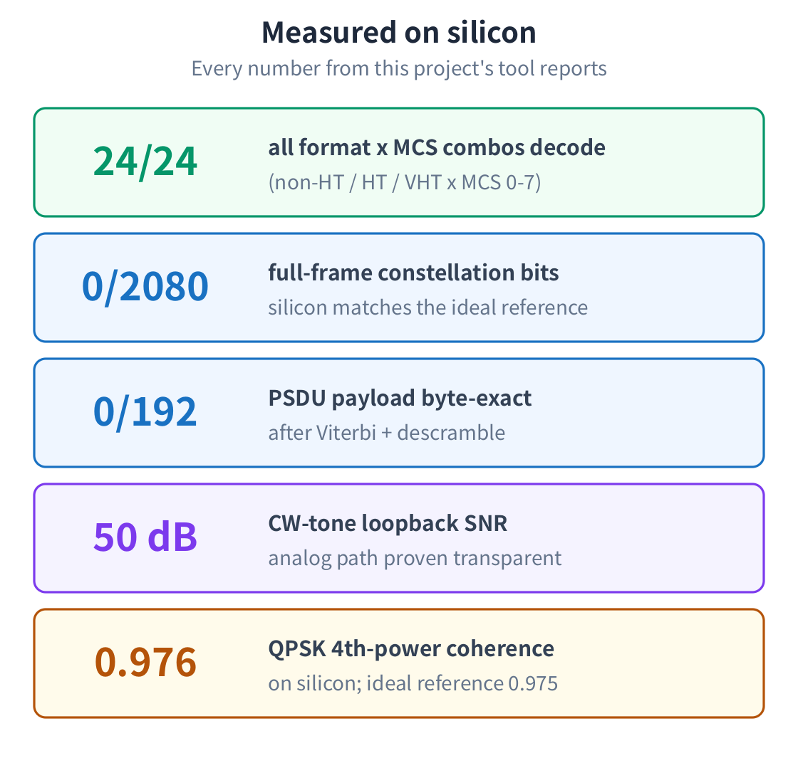
The analog path was also qualified on its own, separately from any modulated signal. A single calibration tone sent through the converters and the cable came back 50 dB above the noise floor with no images, which removes the cable and the converters from suspicion before any decode is discussed.
What we take from it
Both failures shared a shape. Every cheap check passed and the hardware still refused, and in both cases the honest next step was not another guess but a different class of evidence.
For the build defect, that evidence was the netlist the tools actually produced. It costs one extraction from an artifact the build already made, and it turns an expensive hardware iteration into an offline comparison.
For the converter configuration, the evidence was the vendor's own driver source. Reading it takes minutes. A rebuild takes closer to an hour, and five of them were spent before the source was read properly. When a design moves to a newer generation of a device, the honest first move is to inventory every configuration field the new generation added and check each one against a known-good reference, rather than to look up only the field the current theory is about.
And a status flag is not a result. A register saying the frame decoded cost an entire hardware iteration before anyone asked the receiver to hand over the bytes it had actually recovered.
The same discipline runs through everything we do: prove each layer against a real measurement before building the next one on top of it, and trust the state of the machine over what a document says it should be. That is how we bring up boards, and it is the same rigor behind our design services and our verified IP cores. The result is a working system you can measure and log into, proven layer by layer.